6.7. Creating the nodes.ccs File
The nodes.ccs file specifies the nodes that run in a GFS cluster and their fencing methods. The nodes specified include those that run GFS and those that run LOCK_GULM servers. The nodes.ccs file is used in conjunction with the fence.ccs file to configure fencing in a cluster; the nodes.ccs file specifies fencing devices that are defined in the fence.ccs file.
Creating the nodes.ccs file consists of specifying the identity and fencing method (or methods) of each node in a GFS cluster. Specifying the identity consists of assigning a name and an IP address to the node. Specifying a fencing method consists of assigning a name to the fencing method and specifying its fencing-device parameters; that is, specifying how a node is fenced.
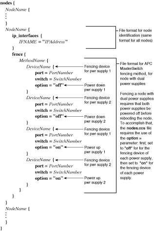
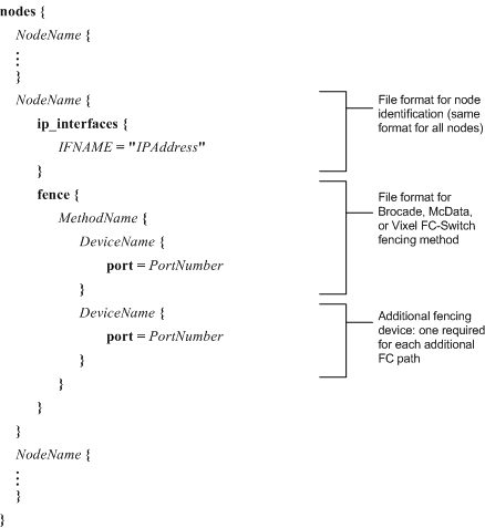
The way in which a fencing method is specified depends on if a node has either dual power supplies or multiple paths to FC storage. If a node has dual power supplies, then the fencing method for the node must specify at least two fencing devices — one fencing device for each power supply. Similarly, if a node has multiple paths to FC storage, then the fencing method for the node must specify one fencing device for each path to FC storage. For example, if a node has two paths to FC storage, the fencing method should specify two fencing devices — one for each path to FC storage. If a node has neither dual power supplies nor multiple paths to FC storage, then the fencing method for the node should specify only one fencing device.
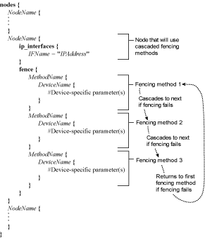
You can configure a node with one fencing method or multiple fencing methods. When you configure a node for one fencing method, that is the only fencing method available for fencing that node. When you configure a node for multiple fencing methods, the fencing methods are cascaded from one fencing method to another according to the order of the fencing methods specified in the nodes.ccs file. If a node fails, it is fenced using the first fencing method specified in the nodes.ccs file for that node. If the first fencing method is not successful, the next fencing method specified for that node is used. If none of the fencing methods is successful, then fencing starts again with the first fencing method specified, and continues looping through the fencing methods in the order specified in nodes.ccs until the node has been fenced.
Refer to Chapter 10 Using the Fencing System for basic fencing details, descriptions of how fencing is used, and descriptions of available fencing methods.
To create the nodes.ccs file, follow these steps:
Create a file named nodes.ccs.
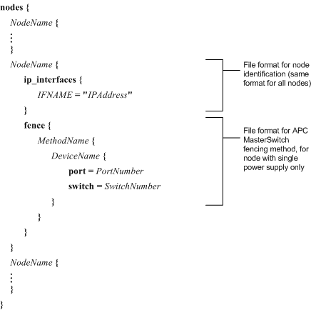
If you are configuring a node for one fencing method (not cascaded), specify only one fencing method per node in the nodes.ccs file. Use a file format according to the fencing method as follows. Refer to Table 6-3 for syntax description.
APC MasterSwitch — For a node with a single power supply, refer to Figure 6-13. For a node with dual power supplies, refer to Figure 6-14.
WTI NPS — Refer to Figure 6-15.
Brocade, McData, or Vixel FC switch — Refer to Figure 6-16.
GNBD — Refer to Figure 6-17.
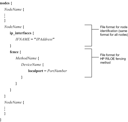
HP RILOE — Refer to Figure 6-18.
xCAT — Refer to Figure 6-19.
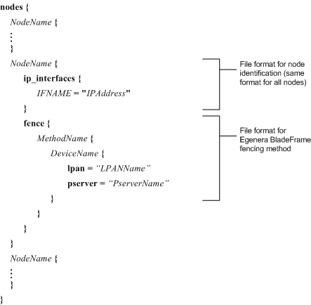
Egenera BladeFrame — Refer to Figure 6-20.
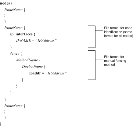
Manual — Refer to Figure 6-21.

Warning Manual fencing should not be used in a production environment. Manual fencing depends on human intervention whenever a node needs recovery. Cluster operation is halted during the intervention.
If you are configuring a node for cascaded fencing, use the file format in Figure 6-22. Refer to Table 6-3 for syntax description.

Note Figure 6-22 does not show device-specific parameters for fencing methods. To determine device-specific parameters, refer to the appropriate figures listed in Step 1, part a.
For each node, specify NodeName, IFName, and the IP address of the node name, IPAddress.
If your cluster is running Red Hat GFS 6.0 for Red Hat Enterprise Linux 3 Update 5 and later, you can use the optional usedev parameter to explicitly specify an IP address rather than relying on an IP address from libresolv. For more information about the optional usedev parameter, refer to the file format in Figure 6-23 and the example in Example 6-26. Refer to Table 6-3 for syntax description of the usedev parameter.
Note Figure 6-23 and Example 6-26 do not show device-specific parameters for fencing methods. To determine device-specific parameters, refer to the appropriate figures listed in Step 1, part a.
Note Make sure that you specify Nodename as the Linux hostname and that the primary IP address of the node is associated with the hostname. Specifying NodeName other than the Linux hostname (for example the interface name) can cause unpredictable results — especially if the node is connected to multiple networks. To determine the hostname of a node, use the uname -n command on the node. To verify the IP address associated with the hostname, issue a ping command to the hostname.
For each node, specify the fencing parameters according to the fencing method you are using, as follows:
If using APC MasterSwitch fencing, specify MethodName, DeviceName, PortNumber, and SwitchNumber. If you are configuring for dual power supplies, specify the following parameters for the second fencing device: DeviceName, PortNumber, and SwitchNumber. Refer to Example 6-13 for a nodes.ccs file that specifies APC MasterSwitch fencing for a single power supply. Refer to Example 6-14 for a nodes.ccs file that specifies APC MasterSwitch fencing for dual power supplies.
If using WTI NPS fencing, specify MethodName, DeviceName, and PortNumber. Refer to Example 6-15 for a nodes.ccs file that specifies WTI NPS fencing.
If using Brocade, McData, or Vixel FC-switch fencing, specify MethodName, DeviceName, and PortNumber. If you are configuring for multiple paths to FC storage, specify the following parameters for each additional fencing device required: DeviceName and PortNumber. Refer to Example 6-16 for a nodes.ccs file that specifies Brocade FC-switch fencing. Refer to Example 6-17 for a nodes.ccs file that specifies McData FC-switch fencing. Refer to Example 6-18 for a nodes.ccs file that specifies Vixel FC-switch fencing.
If using GNBD fencing, specify MethodName, DeviceName, and IPAddress. Refer to Example 6-19 for a nodes.ccs file that specifies GNBD fencing.
If using HP RILOE fencing, specify MethodName, DeviceName, and PortNumber. Refer to Example 6-20 for a nodes.ccs file that specifies HP RILOE fencing.
If using xCAT fencing, specify MethodName, DeviceName, and NodelistName. Refer to Example 6-21 for a nodes.ccs file that specifies xCAT fencing.
If using Egenera BladeFrame fencing, specify MethodName, DeviceName, LPANName, and PserverName. Refer to Example 6-22 for a nodes.ccs file that specifies Egenera BladeFrame fencing.
If using manual fencing, specify MethodName, DeviceName, and IPAddress. Refer to Example 6-23 for a nodes.ccs file that specifies manual fencing.
Warning Manual fencing should not be used in a production environment. Manual fencing depends on human intervention whenever a node needs recovery. Cluster operation is halted during the intervention.
If using cascaded fencing, specify parameters according to the type of fencing methods and in the order that the fencing methods are to cascade. Refer to Example 6-24 for a nodes.ccs file that specifies cascaded fencing.
If using GNBD multipath, fence the GNBD server nodes using any of the fencing methods stated in previous steps in the procedure except for GNBD fencing (Step 3, part d). Refer to Example 6-25 for a nodes.ccs file that specifies fencing for a GNBD server node.
Save the nodes.ccs file.


| Warning |
|---|---|
Manual fencing should not be used in a production environment. Manual fencing depends on human intervention whenever a node needs recovery. Cluster operation is halted during the intervention. |
nodes {
  NodeName {
     ip_interfaces {
         IFNAME="IPAddress"  <-- Must be an IP address; not a name
     }
     usedev = "NamedDevice"  <-- Optional parameter usedev
     fence {
     .
     .
     .
     }
  }
  NodeName {
  .
  .
  .
  }
}
|
Figure 6-23. File Structure: Optional usedev Parameter
| Parameter | Description | |||||
|---|---|---|---|---|---|---|
| DeviceName | The name of a fencing device to use with a node. Use a valid fencing device name specified by a DeviceName parameter in the fence.ccs file (fence.ccs:fence_devices/DeviceName). | |||||
| IFName | The interface name of the IP address specified. For example: eth0 | |||||
| IPAddress |
| |||||
| LPANName | For Egenera BladeFrame fencing: This is the name of the Logical Processing Area Network (LPAN), of which the node (an Egenera pServer) to be fenced is a member. | |||||
| LoginPassword | This is the password of the node to be fenced. | |||||
| MethodName | A name describing the fencing method performed by the listed devices. For example, a MethodName of power could be used to describe a fencing method using an APC MasterSwitch. Or, a MethodName of Cascade1 could be used to describe a cascaded fencing method. | |||||
| NamedDevice | Used with usedev. NamedDevice indicates that the IP address is specified by the optional parameter usedev, and not by the IP address pulled from libresolv. The usedev and NamedDevice parameters are available with Red Hat GFS 6.0 for Red Hat Enterprise Linux 3 Update 5 or later. | |||||
| NodelistName | For xCAT: The node name of the node to be fenced, as defined in the nodelist.tab file. | |||||
| NodeName |
| |||||
| PortNumber |
| |||||
| PserverName | For Egenera BladeFrame fencing: This is the name of an Egenera pServer, the node to be fenced. | |||||
| SwitchNumber | For use with APC MasterSwitch: When chaining more than one switch, this parameter specifies the switch number of the port. This entry is not required when only one switch is present. (The default value is 1 if not specified.) | |||||
| usedev | This is an optional parameter available with Red Hat GFS 6.0 for Red Hat Enterprise Linux 3 Update 5 or later. If usedev is present, GULM uses the IP address from that device in the ip_interfaces section. Otherwise GULM uses the IP address from libresolv (as it does in releases earlier than Red Hat GFS 6.0 for Red Hat Enterprise Linux 3 Update 5). | |||||
| UserId | The user ID of the node to be fenced. |
Table 6-3. File Syntax Description: Variables for nodes.ccs
nodes {
   n01 {
      ip_interfaces {
         hsi0 = "10.0.0.1"
      }
      fence {
         power {
             apc1 {
                port = 6
                switch = 2
             }
          }
       }
  }
  n02 {
  .
  .
  .
  }
} |
Example 6-13. Node Defined for APC Fencing, Single Power Supply
nodes {
   n01 {
      ip_interfaces {
        hsi0 = "10.0.0.1"
      }
      fence {
         power {
            apc1 { <----------- Fencing device for power supply 1
               port = 6
               switch = 1
               option = "off" <-- Power down power supply 1
            }
            apc2 { <----------- Fencing device for power supply 2
               port = 7
               switch = 2
               option = "off" <-- Power down power supply 2
            }
            apc1 { <----------- Fencing device for power supply 1
               port = 6
               switch = 1
               option = "on" <--- Power up power supply 1
            }
            apc2 { <----------- Fencing device for power supply 2
               port = 7
               switch = 2
               option = "on" <--- Power up power supply 2
            }
         }
      }
   }
   n02 {
   .
   .
   .
   }
}
|
Example 6-14. Node Defined for APC Fencing, Dual Power Supplies
nodes {
   n01 {
      ip_interfaces {
         hsi0 = "10.0.0.1"
      }
      fence {
         power {
            wti1 {
               port = 1
            }
         }
      }
   }
   n02 {
   .
   .
   .
   }
}
|
Example 6-15. Node Defined for WTI NPS Fencing
nodes {
   n01 {
      ip_interfaces {
         hsi0 = "10.0.0.1"
      }
      fence {
         san {
            silkworm1 {
               port = 3
            }
            silkworm2 { <--- Additional fencing device, for additional
                port = 4     path to FC storage
            }
         }
      }
   }
   n02 {
   .
   .
   .
   }
} |
Example 6-16. Node Defined for Brocade FC-Switch Fencing
nodes {
   n01 {
      ip_interfaces {
         hsi0 = "10.0.0.1"
      }
      fence {
         san {
            mdfc1 {
               port = 3
            }
            mdfc2 { <--- Additional fencing device, for additional
                port = 4     path to FC storage
            }
         }
      }
   }
   n02 {
   .
   .
   .
   }
} |
Example 6-17. Node Defined for McData FC-Switch Fencing
nodes {
   n01 {
      ip_interfaces {
         hsi0 = "10.0.0.1"
      }
      fence {
         san {
            vixel1 {
               port = 3
            }
            vixel2 { <---- Additional fencing device, for additional
               port = 4    path to FC storage
            }
         }
      }
   }
   n02 {
   .
   .
   .
   }
} |
Example 6-18. Node Defined for Vixel FC-Switch Fencing
nodes {
   n01 {
      ip_interfaces {
         hsi0 = "10.0.0.1"
      }
      fence {
         server {
            gnbd {
               ipaddr = "10.0.1.1"
            }
         }
      }
   }
   n02 {
   .
   .
   .
   }
} |
Example 6-19. Node Defined for GNBD Fencing
nodes {
   n01 {
      ip_interfaces {
         hsi0 = "10.0.0.1"
      }
      fence {
         riloe {
            riloe1 {
               localport = 2345
            }
         }
      }
   }
   n02 {
   .
   .
   .
   }
} |
Example 6-20. Node Defined for HP RILOE Fencing
nodes {
   n01 {
      ip_interfaces {
         hsi0 = "10.0.0.1"
      }
      fence {
         blade-center {
                 xcat {
                    nodename = "blade-01"
            }
         }
      }
   }
   n02 {
      ip_interfaces {
         hsi0 = "10.0.0.2"
      }
      fence {
         blade-center {
                 xcat {
                    nodename = "blade-02"
            }
         }
      }
   }
   n03 {
   .
   .
   .
   }
}
|
Example 6-21. Nodes Defined for xCAT Fencing
nodes {
   n01 {
      ip_interfaces {
         hsi0 = "10.0.0.1"
      }
      fence {
         blade-center {
                egenera {
                   lpan = "opsgroup"
                   pserver = "ops-1
            }
         }
      }
   }
   n02 {
      ip_interfaces {
         hsi0 = "10.0.0.2"
      }
      fence {
         blade-center {
                egenera {
                   lpan = "opsgroup"
                   pserver = "ops-2
            }
         }
      }
   }
   n03 {
   .
   .
   .
   }
}
|
Example 6-22. Nodes Defined for Egenera BladeFrame Fencing
nodes {
   n01 {
      ip_interfaces {
         hsi0 = "10.0.0.1"
      }
      fence {
         human {
            admin {
               ipaddr = "10.0.0.1"
            }
         }
      }
   }
   n02 {
   .
   .
   .
   }
} |
Example 6-23. Nodes Defined for Manual Fencing
| Warning |
|---|---|
Manual fencing should not be used in a production environment. Manual fencing depends on human intervention whenever a node needs recovery. Cluster operation is halted during the intervention. |
   nodes {
      n01 {
         ip_interfaces {
            eth0 = "10.0.1.21"
         }
         fence {
            san {            <-- Fencing with Brocade FC switch
               brocade1 {
                  port = 1
               }
            }
            power {          <-- Fencing with APC MasterSwitch
               apc {
                  port = 1
                  switch = 1
               }
            }
         }
      }
      n02 {
      .
      .
      .
      }
} |
This example shows a node that can be fenced using a Brocade FC switch or an APC MasterSwitch. If the node must be fenced, the fencing system first attempts to disable the node's FC port. If that operation fails, the fencing system attempts to reboot the node using the power switch.
Example 6-24. Nodes Defined for Cascaded Fencing